uSelf-FLC Toolbox
This toolbox contains the proposed methodology to self-evolve a direct fuzzy controller, represented by univariate control rules published in:
Jérôme Mendes, Ricardo Maia, Rui Araújo, and Francisco A. A. Souza. Self-Evolving Fuzzy Controller Composed of Univariate Fuzzy Control Rules. Applied Science, 10(17):5836, August 2020. [doi]
Abstract: The paper proposes a methodology to online self-evolve direct fuzzy logic controllers (FLCs), to deal with unknown and time-varying dynamics. The proposed methodology self-designs the controller, where fuzzy control rules can be added or removed considering a predefined criterion. The proposed methodology aims to reach a control structure easily interpretable by human operators. The FLC is defined by univariate fuzzy control rules, where each input variable is represented by a set of fuzzy control rules, improving the interpretability ability of the learned controller. The proposed self-evolving methodology, when the process is under control (online stage), adds fuzzy control rules on the current FLC using a criterion based on the incremental estimated control error obtained using the system’s inverse function, and deletes fuzzy control rules using a criterion which defines “less active” and “less informative” control rules. From the results on a nonlinear Continuous Stirred Tank Reactor (CSTR) plant, the proposed methodology shows the capability to online self-design the FLC by adding and removing fuzzy control rules in order to successfully control the CSTR plant.
Software source code: uSelf-FLC Toolbox (Matlab implementation)
How to Run
For use with Matlab: - uSelfFLC_Simulink.slx - Open the Simulink file. - Main.m – Just run the Main file.
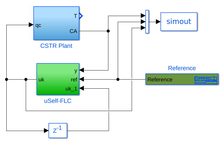
Figure 1: Simulink picture.
Main Functions
Main.m – This is the main function.
Initialization.m - This function initializes the struct x, i.e. the initial parameters (Algorithm 1 Steps 3-8).
- uSelfFLC.m - This function is called on Simulink, which contains all functions of the proposed methodology.
EvolveFLC - This function is the core function to self-evolve the fuzzy controller.
UpdateConsequent - This function updates the consequent parameters (Algorithm 1 Step 10).
FuzzyController_EstimationError – This function obtains the estimated control error (Algorithm 1 Step 12).
LocateMF_Gravity - This function obtains the position/center of the new (candidate) membership function for variable j (Equation (16)).
AddMF_ErrorAVG_newCons - In this function, if Criteria 1 and 2 are met, a new control rules is added on input variable j.
delete_condition - This function deleted control rules, if Criteria 3 and 4 are met (Algorithm 1 Step 22).
DeleteRule - This function deletes the \(i_j\)-th fuzzy control rules of input j.
FuzzyController - This function obtains the fuzzy control signal.
Psi – This function obtains the variable \(\Psi\).
trifp – This function obtains the fuzzy degree of a triangular MF for a given data.
update_window - This function updates the temporal sliding window.
Plot_Evolve_Parameters.m – This function does plots of some important parameters on the evolving stage.
PlotMFs.m - This function presents the plots of the final membership functions of all input variables.
Main Configuration Files
ParametersConfig.m – This file contains the main variables of the algorithm to defined:
data_ref and time ref - Reference defined on the Signal Builder on Simulink
universe_x - Minimum and maximum values of the inputs variables.
control_min_max - Universe of discourse of the control variable [min max].
delta - threshold \(\delta\).
eta_aux - parameters to define the minimal distance between MFs.
epsilon - Thresold \(\epsilon\).
gamma - Learning gain \(\gamma\) (consequents).
T_M - temporal sliding windows size \(T_M\).
Rules_ini - Initial number of fuzzy rules (the same of initial MFs).
safe_interval - minimum number of sample times between the addition of control rules.
Definition of the Struct x
x is a struct, in which, contains all parameters of the fuzzy controller.
Elements of struct x, Rows: contain all parameters of the fuzzy control rules for each input variable, e.g.:
row 1 contains the parameters of the fuzzy control rules for the input variable \(x_1\)
row j contains the parameters of the fuzzy control rules for the input variable \(x_j\)
Figure 1 contains the parameters of the 2 input variables of the CSTR plant example.
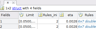
Figure 2: Example of struct x. Final values of the current example, CSTR plant.
Elements of struct x, Columns:
First column: contains the limits of the universe of discourse of the respective input variable.
Second column: contain the initial number of fuzzy control rules of the respective input variable.
Third column: contain the matrix rules of the respective input variable (Figure 3):
Rows: each row represents a fuzzy controlrule;
1º column: represents parameter \(a_{j,i}\) (lower limit of the respective membership function);
2º column: represents parameter \(b_{j,i}\) (center value of the respective membership function);
3º column: represents parameter \(c_{j,i}\) (upper limit of the respective membership function);
4º column: represents the consequent parameter of the respective rule, \(\theta^{i_j}_j\).
5º column: represents the total activation degrees (antecedent values) associated to the \(i_j\)-th fuzzy rule of input \(j\) - Criterion 3.
6º column: represents the sample time at which the fuzzy rule was created - Criterion 3.
7º column: represents the number of times that the antecedent value of \(i_j\)-th fuzzy is the minimum among all the antecedent values - Criterion 3.
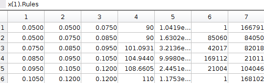
Figure 3: Example of the matrix rules.
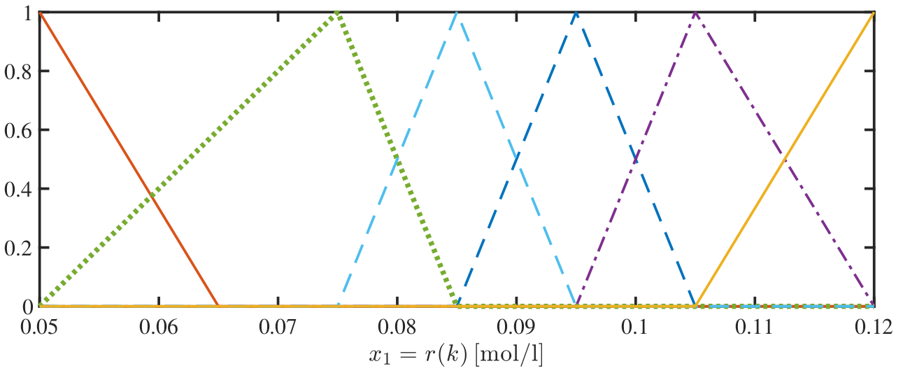
Figure 4: Plot of MFs represented on Figure 2.