
Now that we understand how inputs and outputs are processed by the plc, let's look at a variation of our regular outputs. Regular output coils are of course an essential part of our programs but we must remember that they are only TRUE when ALL INSTRUCTIONS before them on the rung are also TRUE. What happens if they are not? Then of course, the output will become false.(turn off)
Think back to the lunch bell example we did a few chapters ago. What would've happened if we couldn't find a "push on/push off" switch? Then we would've had to keep pressing the button for as long as we wanted the bell to sound. (A momentary switch) The latching instructions let us use momentary switches and program the plc so that when we push one the output turns on and when we push another the output turns off.
Maybe now you're saying to yourself "What the heck is he talking about?". (It's also what I'm thinking!) So let's do a real world example. Picture the remote control for your TV. It has a button for ON and another for OFF.(mine does, anyway) When I push the ON button the TV turns on. When I push the OFF button the TV turns off. I don't have to keep pushing the ON button to keep the TV on. This would be the function of a latching instruction.
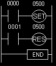
The latch instruction is often called a SET or OTL(output latch). The unlatch instruction is often called a RES(reset), OTU(output unlatch) or RST(reset). The diagram below shows how to use them in a program.

To better understand the above click here and view the animation.
Here's something to think about. What would happen if input 0000 and 0001 both turn on at the exact same time. Will output 0500 be latched or unlatched?? To answer this question we have to think about the scanning sequence. The ladder is always scanned from top to bottom, left to right. The first thing in the scan is to physically look at the inputs. 0000 and 0001 are both physically on. Next the plc executes the program. Starting from the top left, input 0000 is true therefore it should set 0500. Next it goes to the next rung and since input 0001 is true it should reset 0500. The last thing it said was to reset 0500. Therefore on the last part of the scan when it updates the outputs it will keep 0500 off.(i.e. reset 0500).
Makes better sense now, doesn't it??