Math Instructions
Let's now look at using some basic math functions on our data. Many times in our applications we must execute some type of mathematical formula on our data. Its a rare occurrence when our data is actually exactly what we needed.
As an example, lets say we are manufacturing widgets. We don't want to display the total number we've made today, but rather we want to display how many more we need to make today to meet our quota. Lets say our quota for today is 1000 pieces. We'll say X is our current production. Therefore, we can figure that 1000-X=widgets left to make. To implement this formula we obviously need some math capability.
In general, plc's almost always include these math functions:
- Addition- The capability to add one piece of data to another. It is commonly called ADD.
- Subtraction- The capability to subtract one piece of data from another. It is commonly called SUB.
- Multiplication- The capability to multiply one piece of data by another. It is commonly called MUL.
- Division- The capability to divide one piece of data from another. It is commonly called DIV.
As we saw with the MOV instruction there are generally two common methods used by the majority of plc makers. The first method includes a single instruction that asks us for a few key pieces of information. This method typically requires:
- Source A- This is the address of the first piece of data we will use in our formula. In other words its the location in memory of where the first "number" is that we use in the formula.
- Source B- This is the address of the second piece of data we will use in our formula. In other words its the location in memory of where the second "number" is that we use in the formula. -NOTE: typically we can only work with 2 pieces of data at a time. In other words we can't work directly with a formula like 1+2+3. We would have to break it up into pieces. Like 1+2=X then X+3= our result.
- Desination- This is the address where the result of our formula will be put. For example, if 1+2=3, (I hope it still does!!), the 3 would automatically be put into this destination memory location.
The instructions above typically have a symbol that looks like: . Of course, the word ADD would be replaced by SUB, MUL, DIV, etc. In this symbol, The source A is DM100, the source B is DM101 and the destination is DM102. Therefore, the formula is simply whatever value is in DM100 + whatever value is in DM101. The result is automatically stored into DM102.
Here's how to use math functions on a ladder diagram: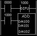
Please note that once again we are using a one-shot instruction. As we've seen before, this is because if we didn't use it we would execute the formula on every scan. Odds are good that we'd only want to execute the function one time when input 0000 becomes true. If we had previously put the number 100 into DM100 and 200 into DM101, the number 300 would be stored in DM102.(i.e. 100+200=300, right??)
The dual instruction method would use a symbol similar to  . In this method, we give this symbol only the Source B location. The Source A location is given by the LDA instruction. The Desination would be included in the STA instruction. Here's a ladder diagram showing what we mean:
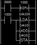
The results are the same as the single instruction method shown above.
To better understand the above click here and view the animation.
What would happen if we had a result that was greater than the value that could be stored in a memory location? Typically the memory locations are 16-bit locations.(more about number types in a later chapter) In plain words this means that if the number is greater than 65535(2^16=65536) it is too big to fit. The we get what's called an overflow. Typically the plc turns on an internal relay that tells us an overflow has happened. Depending on the plc, we would have different data in the destination location.(DM102 above) Most plc's put the remainder here. Some use 32-bit math which solves the problem.(except for really big numbers!) If we're doing division, for example, and we divide by zero(illegal) the overflow bit typically turns on as well. Suffice it to say, check the overflow bit in your ladder and if its true plan appropriately.
Many plc's also include other math capabilities. Some of these functions could include:
- Square roots
- Scaling
- Absolute value
- Sine
- Cosine
- Tangent
- Natural logarithm
- Base 10 logarithm
- X^Y (X to the power of Y)
- Arcsin(tan,cos)
- and more....check with the manufacturer to be sure.
Some plc's can use floating point math as well. Floating point math is simply using decimal points. In other words, we could say that 10 divided by 3 is 3.333333(floating point). Or we could say that 10 divided by 3 is 3 with a remainder of 1(long division). Many micro/mini plc's don't include floating point math. Most larger systems typically do. As always, the theory is always the same, how we implement it is another story. Understand the theory and we can always learn how our manufacturer of choice does it.