What it really means...
Now that we know about response time, here's what it really means
to the application. The PLC can only see an input turn on/off when it's
looking. In other words, it only looks at its inputs during the check input status part of the scan.
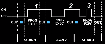
In the diagram, input 1 is not seen until scan 2. This is because when input 1 turned on, scan 1 had already finished looking at the inputs. Input 2 is not seen until scan 3. This is also because when the input turned on scan 2 had already finished looking at the inputs. Input 3 is never seen. This is because when scan 3 was looking at the inputs, signal 3 was not on yet. It turns off before scan 4 looks at the inputs. Therefore signal 3 is never seen by the plc. To avoid this we say that the input should be on for at least 1 input delay time + one scan time.
But what if it were not possible for the input to be on this long? Then the
plc doesn't see the input turn on. Therefore it becomes a paper weight!!!
Not true................ Of course there must be a way to get around
this. Actually there are 2 ways.
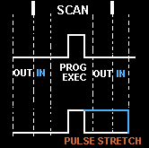
- Pulse stretch function. This function extends the length of the input signal until the plc looks at the inputs during the
next scan. i.e. it stretches the duration of the pulse.
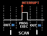
- interrupt function. This function interrupts the scan to process a special routine that you have written. i.e. As
soon as the input turns on, regardless of where the scan currently is, the
plc immediately stops what its doing and executes an interrupt routine. (A
routine can be thought of as a mini program outside of the main program.)
After its done executing the interrupt routine, it goes back to the point
it left off at and continues on with the normal scan process.
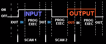
Now let's consider the longest time for an output to actually turn
on. Let's assume that when a switch turns on we need to turn on a load connected to the plc output. The diagram below shows the longest delay(worst case because the input is not seen until scan 2) for the output
to turn on after the input has turned on. The maximum delay is thus 2
scan cycles - 1 input delay time.
It's not so difficult, now is it ???????